Carbide Drill Bit Regrinding: What You Need to Know
Grinding Methods and Techniques of Carbide Drill Bits
Due to the development of high-speed cutting, hard alloy drill bits have also been widely used. Hard alloy drill bits are those with a hard alloy tip welded to the cutting part of the drill bit. They are suitable for high-speed drilling of hard materials such as cast iron, high manganese steel, and quenched steel.
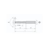
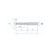
The hard alloy tip material is tungsten carbide K30 (YG8). The geometric parameters of the cutting part are generally: rake angle γo = 0°–5°, clearance angle αo = 10°–15°, point angle 2ϕ = 110°–120°, helix angle ψ = 77°.

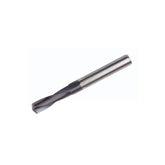
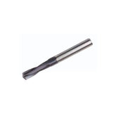
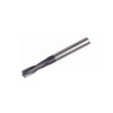
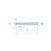
Figure 1: Carbide drill bit with welded tip
To adapt to drilling different materials to achieve different drilling requirements, and to improve some problems existing in standard twist drills, the grinding work done when changing the shape of the cutting part of the drill bit is called grinding.
Grinding Techniques
Grinding the Shank
The purpose is to shorten the shank and increase the rake angle near the drill center. Generally, drill bits with a diameter greater than 5mm need to be ground.
After grinding, the shank length is reduced to 1/3–1/5 of the original. Grinding creates an inner edge with an inner edge angle of 20°–30°, and the rake angle at the inner edge γo=0°–15°.
Grinding the Main Cutting Edge
The purpose is to increase the total length of the cutting edge and the point angle εr, improve heat dissipation conditions, and increase the strength of the teeth.
Generally, 2ϕo=70°–75°, fo=0.2D. This enhances the wear resistance at the intersection of the main cutting edge and the margin, improving the life of the drill bit.
Grinding the Margin
The purpose is to reduce friction on the hole wall and improve the life of the drill bit. Grinding the margin creates a secondary clearance angle α′o=6°–8°.
The margin width is retained to 1/3–1/2 of the original. This technique significantly reduces friction during drilling operations.
Grinding the Front Face
The purpose is to increase the strength of the teeth when drilling hard materials. When drilling brass, it also avoids the phenomenon of sticking caused by the cutting edge being too sharp.
The process involves grinding away part of the front face at the intersection of the main and secondary cutting edges to reduce the rake angle there.
Grinding the Chip Flutes
The purpose is to make the wide chips narrower and facilitate chip removal. Grind several staggered chip flutes on the two rear knife faces.
Drill bits with a diameter greater than 15mm should be ground. This technique is especially valuable when drilling steel.
Grinding the Arc Edge
An arc edge is ground in the middle of the main cutting edge for multi-drill bits. The cutting edge is placed horizontally in contact with the grinding wheel.
The included angle between the drill axis and the grinding wheel plane is the clearance angle αR of the arc edge. This technique requires precise control of arc radius and angles.

Figure 2: Relative position for grinding the shank
Critical Grinding Parameters
| Parameter | Standard Range | Purpose/Effect |
|---|---|---|
| Rake Angle (γo) | 0°–5° | Optimizes cutting edge sharpness |
| Clearance Angle (αo) | 10°–15° | Reduces friction during cutting |
| Point Angle (2ϕ) | 110°–120° | Affects penetration and chip formation |
| Helix Angle (ψ) | 77° | Optimizes chip evacuation |
| Shank Reduction | 1/3–1/5 original | Improves centering and reduces feed force |
| Inner Edge Angle | 20°–30° | Enhances cutting performance |

Figure 3: Grinding the arc edge technique
When using hard alloy drill bits, the feed rate should be smaller to prevent the tip from breaking. The two cutting edges must be ground symmetrically. When the workpiece surface is uneven or there are sand holes in castings, manual feed should be used to prevent damage to the drill bit.
Master Precision Drilling
Explore our premium carbide drill bits collection engineered for optimal performance and durability in all grinding applications.
Explore Drilling Solutions
