Introduction to Carbide Drill Bits - Drill Design
Drill Bit Design
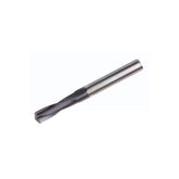
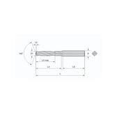
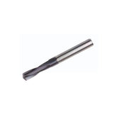
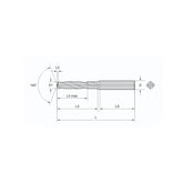
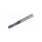
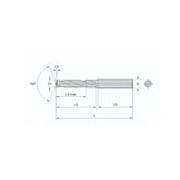
A drill bit is a cutting tool that rotates and feeds along its axis to remove material from a workpiece, creating a hole. The various parts of a drill bit are shown in the figure below.

Design Tip: Proper drill bit design significantly impacts performance, hole quality, and tool longevity.
1. Helix Angle
The helix angle is a crucial factor in forming the drilling entry. It enhances the sharpness of the drill bit and aids in chip removal.
Cutting Edge Strength and Cutting Resistance
The helix angle affects the rake angle and strength of the cutting edge. A larger helix angle increases the rake angle but reduces rigidity.
Chip Removal
A larger helix angle results in a longer chip travel distance, which may slow chip removal and cause clogging due to interference with the hole wall and drill flutes.
The helix angle is typically designed between 15° and 40°:
- For general steel, cast iron, and stainless steel: 20° to 30°
- For non-ferrous metals: 30° to 40°
- For plastics and brass: 15° to 20°
2. Point Angle
The point angle is the angle between the two cutting edges at the drill bit tip.
Chip Handling
Chip handling improves with a larger point angle, per the formula F x COS((180° - point angle)/2). A smaller point angle results in poorer chip handling.

Burr Formation at the Exit
A larger point angle reduces the angle with the outer circumference, making it sharper and reducing burrs. A smaller point angle increases burrs.
Important: The angles between each cutting edge and the centerline must be equal to prevent wobbling, which can cause chipping and hole enlargement.
Common point angles based on material characteristics:
| Material | Point Angle |
|---|---|
| Soft materials | 118° |
| Alloy steel | 140° |
| Stainless steel | 135° |
| Hardened steel | 130°-140° |
| Plastics | 90°-100° |
3. Lip Relief Angle
The lip relief angle, formed between the cutting edge and the drill bit face, prevents damage from workpiece springback and reduces friction. It depends on the material's Young's modulus and toughness.
- General steel: 10° to 13°
- Hardened steel: 6° to 9°
- Stainless steel: 8° to 12°
- Aluminum: 12° to 16°
- Plastics: 15° to 20°
4. Chisel Edge and Chisel Edge Thinning
The chisel edge, or dead center, is the intersection of the two faces at the drill bit tip, perpendicular to the drill axis. It can cause the drill to walk if not concentric with the axis, leading to wobbling, breakage, and hole enlargement.

Non-thinned chisel edges generate large thrust loads, increasing with length. X-shaped thinning shortens the chisel edge, nearly eliminating thrust load, reducing vibration-related chipping and burrs, and improving hole accuracy.
Performance Note: Proper chisel edge thinning can reduce thrust force by up to 60% and improve hole accuracy significantly.
5. Main Cutting Edge and K-Land
The main cutting edge is the intersection of the drill flute and face at the tip. The angles and lengths of the two cutting edges must be equal to avoid uneven cutting, which can dull or crack the edge, enlarge the hole, or cause wobbling.
A K-Land width design can increase lifespan by 40% to 60% by providing additional support to the cutting edge and reducing chipping.
6. Blade Land
Functions of the blade land:
- Maintains drill bit size
- Supports the hole wall and guides the drill bit, stabilizing drilling
Functions of double blade land:
- Improves dimensional and shape accuracy (roundness) of the hole
- Enhances hole surface quality
- Provides stability for deep hole drilling
Considerations for blade land width:
- Widen for hole straightness and accuracy
- Narrow for work-hardening materials like stainless steel, where heat causes surface hardening
7. Taper
Function of taper: Reduces friction between the outer blade land and hole wall.
- Typical taper: 0.03 to 0.1 mm per 100 mm length
- For high-speed drilling or elastic/sticky materials: 0.2 to 0.4 mm
Application Tip: When drilling deep holes or working with materials prone to galling, increased taper helps prevent binding and heat buildup.
