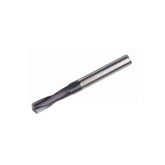
Introduction to Carbide Drill Bit Technology
Carbide Drill Bit Technology
Advanced geometric characteristics of conical back rake drill tips and their application in grinding wheel usage for superior performance and durability.
Geometric Characteristics
The conical back rake drill tip features a unique geometry that enhances drilling performance across various materials. This design reduces cutting forces, improves chip evacuation, and extends tool life.

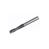
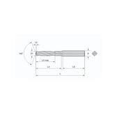
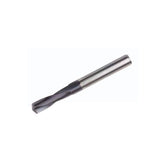
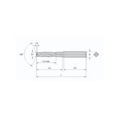
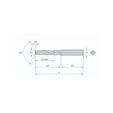
Geometric structure of the conical back rake drill tip showing key angles and surfaces
✓ Key Geometric Features
- Conical relief angle for reduced friction
- Optimized point angle (118°-140°) for material-specific performance
- Precisely calculated rake angle for optimal chip formation
- Specialized clearance angles for different materials
- Chisel edge geometry for improved centering
✓ Performance Benefits
- Increased tool life by 40-60%
- Reduced thrust force by 20-30%
- Improved hole quality and surface finish
- Higher penetration rates in hard materials
- Reduced vibration and chatter during operation
Technical Specifications
| Parameter | Standard Value | Range | Application |
|---|---|---|---|
| Point Angle | 135° | 118°-140° | General purpose |
| Helix Angle | 30° | 25°-40° | Most materials |
| Clearance Angle | 8° | 6°-12° | Hard materials |
| Rake Angle | 5° | 0°-10° | Steel alloys |
Grinding Wheel Structure
A bowl-shaped grinding wheel (Type 12A2) with a zero-degree dish angle on its front side is essential for grinding the conical back rake of the drill tip. The front surface must be perfectly flat for precision grinding.

Two-wheel grinding set configuration for precision drill bit production
✓ Grinding Wheel Specifications
- Type: 12A2 Bowl-shaped wheel
- Dish Angle: 0° (flat front surface)
- Grit Size: 80-120 for roughing, 150-220 for finishing
- Bond Type: Vitrified bond for carbide grinding
- Concentration: 75-100 for carbide tools
✓ Installation Guidelines
- Mount at the front of the grinding wheel set
- Ensure proper wheel balancing before operation
- Maintain correct wheel orientation (flat side outward)
- Use appropriate wheel guards and safety measures
- Regularly dress the wheel to maintain flat profile
Optimal Grinding Parameters
| Operation | Wheel Speed (m/s) | Feed Rate (mm/min) | Coolant |
|---|---|---|---|
| Rough Grinding | 25-30 | 100-150 | Flood coolant |
| Finish Grinding | 30-35 | 50-80 | Flood coolant |
| Form Grinding | 20-25 | 30-50 | Mist coolant |
Distance from the Cutting Edge Start to the Cone Apex
The precise measurement from the cutting edge start to the cone apex is critical for optimal drill performance. This distance affects chip formation, heat dissipation, and tool stability during operation.

Measurement from cutting edge start to cone apex
✓ Measurement Guidelines
- Standard range: 0.5-1.5mm for most applications
- Varies based on drill diameter and material
- Precision tolerance: ±0.05mm
- Measured using optical comparators or CMM
- Critical for maintaining concentricity
✓ Impact on Performance
- Shorter distance: Increased rigidity
- Longer distance: Better chip evacuation
- Optimal balance depends on application
- Affects tool life and hole quality
- Influences cutting forces and vibration
Recommended Distances by Drill Size
| Drill Diameter (mm) | Min Distance (mm) | Max Distance (mm) | Optimal Distance (mm) |
|---|---|---|---|
| 3-6 | 0.4 | 0.8 | 0.6 |
| 6-10 | 0.6 | 1.0 | 0.8 |
| 10-16 | 0.8 | 1.2 | 1.0 |
| 16-25 | 1.0 | 1.5 | 1.2 |
